How Electrical Contactor Wiring Control a Motor
Knowing how to wire an electrical contactor in industrial and commercial applications is an important step for managing electric motor operation. This post reviews electrical contactor wiring, how electric contactors work, and introduces standard electrical contactor wiring diagram instructions to help you when selecting and installing Contact Kits and Motor Control Parts.
Need Electrical Contactors?
Get My QuoteSell To Us
Got Electrical Equipment You Don't Need?

Reduce Your Electrical Inventories & Earn Cash
Sell My EquipmentPanelboard
Need a Panelboard for Your Project/Job?
Our Experienced Sales Engineers Can Help Design the Right Panelboard For You
Learn MoreTransformer Oil Testing
Is Your Transformer Due For Servicing?
Get Your Oil Analysis & Fluid Testing Done By Our NETA-Certified Techs
Learn MoreElectrical Product Resources
Product Training Product Safety Product Guides Product News Featured ProductsWhat’s a Contactor?
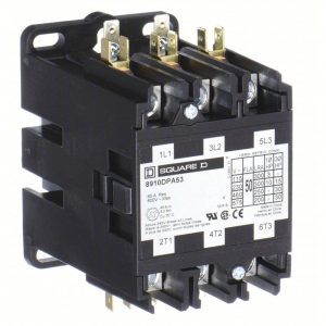
An electric motor contactor is an electromagnetic switch used to control the flow of power to an electric motor. As a motor control accessory, It includes a coil, which is usually connected to a low-voltage control circuit, and a set of contacts, which regulate the high-voltage power circuit to the motor. When a voltage is applied to the coil, an electromagnetic field is created, which attracts a movable armature.
This movement shuts the contacts, allowing current to flow from the power supply to start the motor. When the coil is de-energized, the contacts open, shutting down the motor. Contactors play an important role in remote motor control and overload prevention.
Steps for Wiring an Electric Contactor in a Motor
- Start electric contactor wiring by making sure the motor circuit’s power supply is entirely cut off by using a circuit breaker or disconnect switch. Always confirm that the circuit is in fact de-energized with a voltage tester. Next, choose a contactor that is compatible with the control voltage utilized in your system and fits the voltage and current demands of your motor. Install the contactor firmly on a suitable surface, like a control panel or a motor control hub.
- Find the contactor’s control terminals frequently labeled as “A1” and “A2” for coil connections. One end of a control wire should be connected to the “A1” terminal, and the other end should be connected to the control voltage source, which is usually a control transformer. By attaching the control wire’s other end to the “A2” terminal, the control circuit is finished.
- Continue by connecting the motor wiring. Find the contactor’s power connections, which are often marked “L1,” “L2,” and “L3” for three-phase motors.
- Three of the motor power wires should be connected: one to the “L1” terminal, one to the “L2,” and one to the “L3.” The opposite ends of these power wires should then be connected to the motor’s corresponding terminals.
- Consider connecting overload relays in series with the motor power wires for improved motor safety, but make sure these relays are the right size for the motor’s current rating. After establishing the control circuit, activate the control voltage source to energize the contactor’s coil. The power circuit of the contactor will be closed as a result, starting the motor.
- Always consult manufacturer documentation for your particular contactor and motor. Work should only be performed by certified electricians.
3-Phase Electric Motor Contactor Wiring Example
Three-phase motors are the most common type for industrial and commercial applications. They operate on three separate AC voltage supplies, each 120 degrees out of phase with the others. Three-phase motors offer high efficiency, high starting torque, and smoother operation, making them ideal for heavy machinery, pumps, compressors, and more. They are also more reliable and require less maintenance compared to single-phase motors.
The electric contactor wiring table below provides a basic overview; actual electric contactor wiring schematics might be more complex and detailed based on the motor and control system needs. See the manufacturer’s literature and wiring diagram for details about your particular motor and contactor configuration.
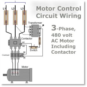
3-Phase Electric Motor Wiring Diagram Labels and Symbols
| Symbol/Label | Description |
| L1, L2, L3 | Three-phase power supply lines (Hot wires) |
| T1, T2, T3 | Motor terminals for three-phase power (Connection to motor windings) |
| A1, A2 | Control coil terminals (Low Voltage) |
| Start/Stop | Push-button switches to manually start and stop the motor |
| OL | Overload relay for motor protection (may include trip contacts) |
| F | Fuse for motor circuit protection |
| M | 3-phase Motor |
| Ground | Grounding connection for safety |
| NO | Normally Open contact (used for control functions) |
| NC | Normally Closed contact (used for control functions) |
| Coil Voltage | Voltage required to energize the contactor coil (e.g., 120V, 240V) |
| Control Voltage Source | Power source for the control circuit that energizes the contactor coil |
Power Connection Instructions for Contactors in a 3-Phase Motor
Power Connections: Connect L1, L2, and L3 (the three-phase power supply lines) to the corresponding motor terminals T1, T2, and T3.
Control Circuit: Identify the control coil terminals A1 and A2. Connect them to the control voltage source (typically low voltage).
Push-button Start and Stop: switches to manually control the motor’s operation by breaking or completing the control circuit.
Motor Protection: Look for an overload relay (OL) and any associated trip contacts in the diagram. The overload relay provides motor protection by tripping if the motor draws excessive current.
NO (Normally Open) or NC (Normally Closed): These additional contacts can be used for various control functions in the motor circuit.
Safety Ground: Ensure that the motor and control circuit are properly grounded for safety.
Fuses: Check for fuses in the motor circuit. They are used for circuit protection and may be labeled as F.
Types of Contactors for Electric Motors
AC contactors are extensively used in industrial and commercial applications to regulate AC motors. They come in a variety of sizes and configurations to handle varying voltage and current ratings.
DC Contactors: DC contactors are used to drive DC motors and are commonly utilized in applications requiring precision motor control, such as electric vehicles and robots.
NEMA Contactors: NEMA (National Electrical Manufacturers Association) contactors are intended to meet NEMA specifications. They are available in a variety of NEMA frame sizes and are compatible with NEMA motor starters and enclosures.
IEC Contactors: IEC (International Electrotechnical Commission) contactors conform to international motor control component standards. They are widely used in Europe and other places that adhere to IEC specifications.
Definite Purpose Contactors: These are specialist contactors developed for certain purposes such as air conditioning, heating, and refrigeration. They are frequently small and inexpensive.
Reversing Contactors: Reversing contactors are used to change the rotational direction of a three-phase motor. They contain two sets of primary contacts and are commonly used in conveyor systems and winches.
Contactor starters: Used to safeguard the motor from overcurrent circumstances and feature overload protection. In a single unit, they combine a contactor with an overload relay.
Mini contactors are compact and space-saving contactors that are ideal for applications with limited installation space. They are frequently seen in control panels and tiny machinery.
Magnetic contactors are devices that use magnetic forces to close.
Vacuum Contactors: Use a vacuum as the arc-quenching medium when opening and closing contacts. They’re ideal for high-voltage, high-current applications like heavy motors and power distribution.
Solid-State Contactors: Solid-state contactors manage the power to the motor using semiconductor devices such as thyristors. They are frequently utilized in applications that need precise control and minimal contact wear and tear.
Electronic contactors: comparable to solid-state contactors, but they include extra characteristics like as overload safety, soft-start capabilities, and complex control options.
The contactor type used is determined by requirements such as the voltage and current needs of the motor, the demands of the application, and any unique features or standards required. To ensure the safe and effective running of 3-phase motors, the proper contactor must be selected.
Understanding Contactors, Wiring to Select Motor Control Parts
Knowing how to wire an electrical contactor is an essential skill for everyone involved in industrial or commercial operations where electric motors are at the heart of productivity. We’ve looked at the principles of electrical contactor wiring and the mechanics of how these vital components work. You should now have a basic understanding of electrical contactor wiring diagrams for picking the right electrical contactor for the job.