This table of symbols used in a motor control wiring diagram is intended for electrical technicians and engineers involved in the construction and maintenance of motor starting wiring systems. It offers a thorough understanding of the essential components and symbols found in motor starter wiring schematics.
Recognizing these symbols is critical for appropriate wiring, optimal motor performance, and avoiding possible problems. Technicians benefit from obtaining a better grasp of circuit layout, which enables more effective troubleshooting, maintenance, and precise control over motor operations. With this knowledge, a trained motor control technician can replace faulty electric motor starters.
Need Motor Control Products?
Get A QuoteSell To Us
Got Electrical Equipment You Don't Need?

Reduce Your Electrical Inventories & Earn Cash
Sell My EquipmentPanelboard
Need a Panelboard for Your Project/Job?
Our Experienced Sales Engineers Can Help Design the Right Panelboard For You
Learn MoreTransformer Oil Testing
Is Your Transformer Due For Servicing?
Get Your Oil Analysis & Fluid Testing Done By Our NETA-Certified Techs
Learn MoreElectrical Product Resources
Product Training Product Safety Product Guides Product News Featured ProductsMotor Control Wiring Symbols and What They Mean
| Item | Purpose | Symbol |
|---|---|---|
| Circuit Breaker | Provides overcurrent protection and can be manually reset, used for short circuit protection. In a motor control wiring diagram, a circuit breaker represents improved safety from excessive current. | 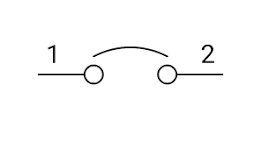 |
| Contactor | An electromechanical switch that controls power to the motor, allowing start and stop functionality. Understanding contactors in a wiring diagram identifies the primary switch for motor control. | 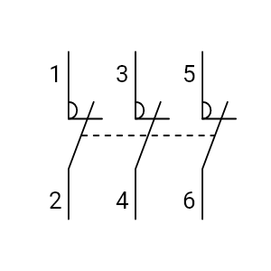 |
| Diode | Allows current flow in one direction, used for rectification or preventing backflow in certain circuits. Diodes, depicted in diagrams, determine current direction and are important for preventing unwanted power flows. | |
| Fuses | Protect the electrical circuit by breaking it if the current exceeds specified limits. Represented in diagrams, fuses show protected components and help identify potential circuit issues. | 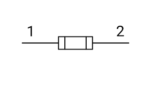 |
| Ground Symbol | Represents the grounding point for a safe path for fault currents to reduce electrical shock risk. In wiring diagrams, the ground symbol represents the point where fault currents are safely directed. | 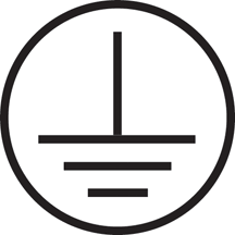 |
| Inductor | Stores energy in a magnetic field, employed in motor control circuits for filtering or delaying current changes. Inductors in diagrams this symbol represents energy storage, influencing the timing and stability of the circuit. | 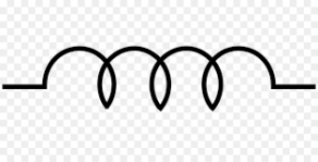 |
| Motor Starter | A device that controls the electrical power to the motor, ensuring safe and efficient motor operation. In wiring diagrams, motor starters show power regulation, enhancing the overall safety and performance. | 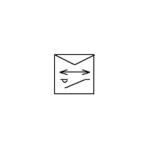 |
| Overload Relay | Protects the motor from overheating by monitoring and tripping the circuit in case of excess current. Overload relays in a motor control wiring diagram, shows motor damage prevention that detects and responds to high currents. | 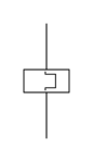 |
| Resistors | Control the flow of current, often limiting current to specific components in the control system. In diagrams, resistors show where current flow is dictated, influencing the behavior of components within the circuit. | 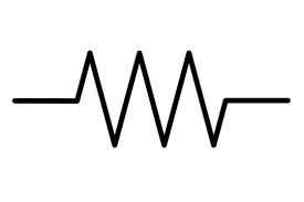 |
| Run Capacitor | Improves power factor and efficiency during continuous motor operation. Represented in diagrams, run capacitors optimize motor efficiency by enhancing power factor. | 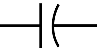 |
| Start Capacitor | Enhances motor starting by providing an additional phase shift for improved torque. Start capacitors, illustrated in diagrams, aid in smoother motor starting by adjusting phase angles. | |
| Start Stop Push Button | Allows manual starting and stopping of the motor, providing basic control. Displayed in diagrams, push buttons offer manual control, allowing users to start and stop the motor. | 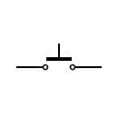 |
| Switch | Controls the flow of electrical power, facilitating manual or automatic on/off control of the motor. Switches, visualized in diagrams, are crucial for controlling power flow and motor operation. | 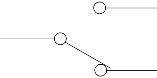 |
| Terminal Blocks | Provides an organized way to connect and terminate wires, aiding in maintenance and troubleshooting. Terminal blocks in a motor control wiring diagram simplify wiring making connections, enhancing maintenance and troubleshooting. | 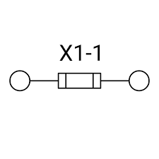 |
Why Understand Motor Wiring Diagrams?
As a tech, this table of symbols for motor control wiring should give you useful insights into key components and symbols. Recognizing these symbols is important for appropriate wiring, which helps the motor runs safely and effectively. With this understanding, you are one step closer to control over motor operations. This allows you to be more confident around electrical systems in industrial settings. The more you learn, the more you earn!
IMPORTANT: Electrical systems can be hazardous, and working with them without the necessary expertise and training can be dangerous. If you’re not a qualified electrician or don’t have experience diagnosing a bad starter, it’s highly recommended to get the assistance of a certified electrical professional. Performing electrical work without the needed knowledge and training may lead to severe injuries, electric shocks, or damage to the equipment. Always prioritize safety and, when in doubt, contact a qualified electrician about how to replace a bad electrical starter and related electrical maintenance.