Contactors are the unsung heroes of modern-day electrical systems.
These often-overlooked devices play a crucial role in keeping our homes, businesses, and industries running smoothly.
Contactors are versatile and widely used in industrial, commercial, and residential applications. Some applications you might recognize include electric motors, lighting circuits, and heating and cooling systems. Suffice to say, contactors ensure the safe and reliable operation of electrical systems and equipment.
Need Contactors For Your Project?
Get A Contactor QuoteSell To Us
Got Electrical Equipment You Don't Need?

Reduce Your Electrical Inventories & Earn Cash
Sell My EquipmentPanelboard
Need a Panelboard for Your Project/Job?
Our Experienced Sales Engineers Can Help Design the Right Panelboard For You
Learn MoreTransformer Oil Testing
Is Your Transformer Due For Servicing?
Get Your Oil Analysis & Fluid Testing Done By Our NETA-Certified Techs
Learn MoreElectrical Product Resources
Product Training Product Safety Product Guides Product News Featured ProductsIn this article, we will explore five main questions:
What is a Contactor?
A contactor, not to be confused with a “contractor”, is an electromechanical device used to control the switching and protection of high-power loads. It is essentially a heavy-duty relay capable of handling large amounts of electrical current and voltage.
They have a simple yet elegant anatomy that typically consists of several parts:
| Coil | This generates a magnetic field when an electrical current is passed through it |
| Contacts | Metal plates typically made of materials that can withstand high temperatures and electrical currents |
| Armature | A movable part that is attached to the contacts |
| Spring | This opens the contacts and interrupts the current flow |
| Auxiliary Contacts | Additional sets of contacts that are typically located on the side of the contactor and are used to control other circuits |
| Housing | The outer casing typically made of a durable material, such as plastic or metal |
| Overload and Thermal Protection | Some contactors have these built-in to prevent damage to the contactor and the connected circuit |
How Do Contactors Work?
Contactors use an electrical current to control the opening and closing of a set of contacts.
When current is applied to the coil, it is considered energized. This creates a magnetic field that attracts the contacts to each other. The armature moves and allows the contacts to close, which closes and completes the circuit. The current now flows through the connected circuit, enabling the device being controlled to operate.
Once the electrical current to the coil is removed, it is considered de-energized. The magnetic field collapses and the spring returns the armature to its original position. This opens the contacts, interrupts the current flow, and breaks the circuit.
A contactor typically has multiple sets of contacts, allowing it to switch multiple circuits simultaneously. It also may have additional features, such as overload protection or thermal protection, which can protect the contactor and the connected circuit from damage due to excessive current or overheating.
Types of Contactors
There are several types of contactors, and below are five most common ones.
AC & DC Contactors
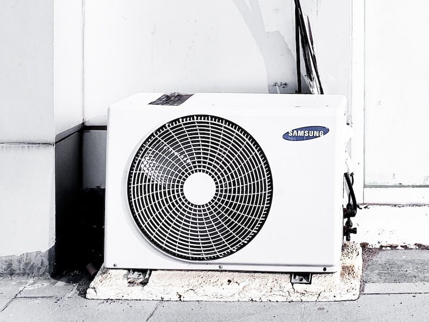
Alternating current (AC) power works with AC contactors, and direct current (AC) power works with DC contactors. AC and DC contactors are typically used in applications where high current loads need to be switched on and off, such as in air conditioning units, and refrigeration systems (AC contactors), and electric vehicles, and battery-powered equipment applications (DC contactors).
AC CONTACTORS PROS
- Efficient and cost-effective way of controlling AC circuits
- Can handle high voltage and current ratings
- Offer good switching performance and reliability – typically made of high-quality materials designed to withstand harsh environments, temperature fluctuations, and frequent use
- Can be used for a wide range of applications, including lighting, heating, and motors
- Easy to install and maintain
AC CONTACTORS CONS
- Cannot be used for DC circuits
- May require additional components for complete circuit protection, such as overload relays
- May generate heat and require cooling mechanisms to prevent damage to the contactor
- May produce an audible buzzing noise during operation, which may be undesirable in some applications
- Can produce electromagnetic interference (EMI)
DC CONTACTORS PROS
- Efficient and cost-effective way of controlling DC circuits
- Can handle high voltage and current ratings
- Offer good switching performance and reliability – typically made of high-quality materials designed to withstand harsh environments, temperature fluctuations, and frequent use
- Can be used for a wide range of applications, including motors, generators, and battery systems
- Easy to install and maintain
DC CONTACTORS CONS
- Cannot be used for AC circuits
- May require additional components for complete circuit protection, such as snubber circuits (fuses, breakers)
- May generate heat and require cooling mechanisms to prevent damage to the contactor
- May produce an audible buzzing noise during operation, which may be undesirable in some applications
- May require special consideration for arc suppression due to DC’s tendency to sustain arcs
Definite Purpose Contactors
Definite Purpose Contactors (DPCs) are a type of contactor designed for specific applications, such as lighting, HVAC, air conditioning, refrigeration, and heating systems. They are typically used in commercial and industrial settings where reliable and efficient electrical control is needed.
DPCs are designed to handle a specific load with a fixed horsepower or amperage rating and are not intended for general-purpose use. They are often used in conjunction with other electrical components, such as motor starters and overload relays, to provide complete control of the system.
Depending on the specific application requirements, they may come in various types and configurations, such as magnetic or electronic. Some may also be designed for special features such as noise reduction, arc suppression, or voltage surge protection.
PROS
- Relatively inexpensive, making them a cost-effective solution for specific applications
- Designed for specific applications and are highly reliable in their operation
- Typically smaller in size than general-purpose contactors, making them ideal for installations where space is limited
- Lower risk of wear and tear, requiring less maintenance
- Straightforward and quick installation
CONS
- Limited functionality and may not be suitable for other applications
- Limited customization – users cannot tailor them to their specific requirements
- Shorter lifespan than other types of contactors due to their limited use and design
- Limited flexibility and cannot be easily reconfigured for other uses
- May not be readily available in the market
Magnetic contactors
These contactors are commonly used in motor control applications, providing a safe and reliable method of starting, stopping, and reversing the direction of a motor.
Depending on the system’s requirements, magnetic contactors can be operated manually or automatically. They may also include features such as overload protection, auxiliary contacts for signaling, and interlocks to prevent unauthorized access or unsafe operation.
PROS
- Reliable operation
- Long lifespan
- High switching capacity
- Can handle high inrush currents
- Low power consumption
CONS
- Large physical size
- Can produce a loud clicking sound when switched
- Can be more expensive than electronic alternatives
- Limited switching speed compared to electronic alternatives
- Not suitable for high-frequency switching applications
Reversing Contactors
These contactors are designed to reverse an electric motor’s rotation direction. They are commonly used in industrial applications where motors are frequently required to change direction.
Reversing contactors consist of two contactors that are mechanically and electrically interlocked. When the control circuit is energized, one contactor closes to start the motor in one direction. When the motor needs to reverse, the second contactor closes to reverse the direction of the motor.
They are typically rated for high-duty cycles and are designed to withstand frequent switching between forward and reverse modes without wearing out or overheating.
Depending on the motor rating and application requirements, reversing contactors may come in various sizes and types, such as NEMA or IEC. They may also include additional features such as overload protection, surge suppression, or noise reduction.
PROS
- Provide a simple and reliable method of reversing the direction of a motor’s rotation
- Often used in applications where precise control over a motor’s speed and direction is required
- Cost-effective solution compared to other methods of reversing motor rotation
- Relatively easy to install and maintain
CONS
- May produce significant electrical noise and cause interference in nearby electronic equipment
- May not provide the precise control over a motor’s speed and direction required for some applications
- Can experience mechanical wear and tear over time, which can result in reduced reliability and increased maintenance costs
- In some cases, may not be suitable for use with high-speed or high-torque motors
Latching Contactors
These contactors, also known as bistable or impulse relays, are contactors that use a mechanical latching mechanism to maintain its state after the control circuit has been de-energized. This means the contactor does not need continuous power to keep its contacts closed or open.
Latching contactors are typically used in specific applications and may not be suitable for all use cases. They are commonly used in applications where power is limited or a continuous power supply is impractical, such as in remote or battery-operated systems and emergency stop circuits.
Latching contactors can be operated by a momentary pulse of voltage or current, which a switch, timer, or other control devices can supply. Some latching contactors may also include a manual override feature to change the state of the contacts manually.
PROS
- Require less energy to maintain their state than other types of contactors, which can result in energy savings and lower operating costs
- Often smaller and more compact than other types of contactors, which can save space in control panels and equipment
- Can be very reliable when used in the right applications, as long as they are properly designed and maintained
- Usually less expensive than other traditional contactors, which can make them a cost-effective choice for some applications
CONS
- Can suffer from contact welding, which can cause them to stick in the closed position and fail to open when needed
- The latching mechanism requires a continuous current flow to maintain the contactor’s state, which can cause the coil to overheat and burn out
- Require power to maintain their state, so a power loss could cause them to switch off and require manual resetting
- In some applications, the latching mechanism may not provide the level of safety required – for example, if power is lost, a latching contactor may not be able to open, potentially leading to a safety hazard
NEMA and IEC
You may have heard of NEMA and IEC if you work in the electrical industry. If not, let’s review these two standards in general and specifically to contactors.
NEMA
The National Electrical Manufacturers Association (NEMA) is a trade association in the United States (and widely recognized worldwide) representing manufacturers of electrical equipment and medical imaging technologies. NEMA develops standards to ensure that electrical equipment is safe, reliable, and performs as intended.
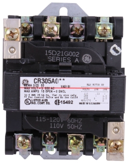
A NEMA contactor is designed and manufactured in accordance with NEMA standards. These standards specify the physical dimensions, ratings, and performance characteristics of contactors in various electrical applications.
One of the key features of NEMA contactors is their standardized sizing and mounting configurations. This allows for easy replacement and interchangeability between different brands and manufacturers. NEMA contactors are also designed to meet specific performance standards, such as their ability to withstand voltage spikes and operate in high-temperature environments.
NEMA contactors are available in various sizes and ratings to suit different applications. When selecting a NEMA contactor, you must choose the appropriate size and current rating to ensure safe and reliable operation in your specific application.
Below are the most common NEMA sizes for contactors:
| NEMA Size | Current Rating |
| 00 | Small contactors that can handle up to 10A |
| 0 | Contactors that can handle up to 20A |
| 1 | Contactors that can handle up to 30A |
| 2 | Contactors that can handle up to 90A |
| 3 | Contactors that can handle up to 200A |
| 4 | Contactors that can handle up to 300A |
| 5 | Contactors that can handle up to 600A |
Note that the maximum voltage rating of a contactor also depends on the application and the specific contactor model. For example, some contactors may be rated for higher voltages than others within the same NEMA size. It is essential to check the manufacturer’s specifications to ensure it is rated for the appropriate voltage for your application.
IEC
International Electrotechnical Commission (IEC) develops standards for electrical, electronic, and related technologies. Similar to NEMA, IEC standards are designed to ensure that electrical and electronic equipment is safe, reliable, and performs as intended, regardless of where it is manufactured or used.
IEC contactors are widely used in Europe, Asia, and other parts of the world.
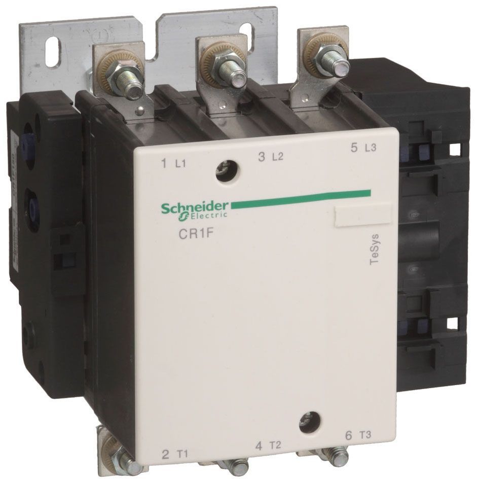
They come in a range of sizes, from the smallest miniature contactors to the largest power contactors. IEC contactors are rated for different current levels and voltages. They are typically designated by a “frame size” and a “rated operational current” (Ie). The frame size represents the physical size of the contactor, while the rated operational current represents the maximum continuous current that the contactor can carry.
IEC contactors are designed to be modular, with interchangeable parts, making them easy to maintain and repair. They incorporate features, such as arc chutes, which help extinguish any arcs occurring when the contactor switches off.
Below is a general list of IEC contactor frame sizes and their corresponding rated operational currents:
| Frame Size | Rated Operational Current |
| A | Up to 16A |
| B | Up to 32A |
| C | Up to 63A |
| D | Up to 100A |
| E | Up to 150A |
| F | Up to 250A |
| G | Up to 400A |
| H | Up to 630A |
| J | Up to 800A |
| K | Up to 1000A |
Note that these are general guidelines, and the specific ratings and sizes may vary depending on the manufacturer and the particular contactor model.
NEMA Contactors vs. IEC Contactors
One of the main differences between IEC and NEMA contactors is their construction. NEMA contactors are typically larger and heavier than IEC contactors, and are designed with a more rugged construction. IEC contactors, on the other hand, are generally more compact, lightweight, and less expensive.
Another difference is their ratings. NEMA contactors are rated according to horsepower (hp), while IEC contactors are rated according to kilowatts (kW). Additionally, the rated operational currents for NEMA contactors are typically higher than those for IEC contactors.
They also differ in mounting and accessories. NEMA contactors are usually mounted on a panel, while IEC contactors can be mounted on a panel or a DIN rail. Compared to NEMA contactors, IEC contactors typically offer a wider range of accessories, such as auxiliary contacts, overload relays, and timers.
Although both IEC and NEMA contactors provide protection against overloads and short circuits, there are some differences in their design and performance in these situations.
IEC contactors typically use thermal overload relays to protect against overloads. These relays are typically mounted directly onto the contactor and can be adjusted to trip at a specific current level. In the event of an overload, the thermal overload relay will open the contactor and interrupt the circuit.
On the other hand, NEMA contactors may use either thermal overload relays or electronic overload relays to protect against overloads. Electronic overload relays are typically more accurate and can respond more quickly to overloads, which can help minimize system damage.
When it comes to short circuits, both IEC and NEMA contactors are designed to handle high fault currents. IEC contactors typically have a higher short-circuit rating than NEMA contactors, which means they can handle higher fault currents without sustaining damage.
The choice between a NEMA contactor and an IEC contactor depends on your specific application and the requirements of the electrical system.
Applications
The choice between a NEMA contactor and an IEC contactor depends on your specific application and the requirements of the electrical system.
We have touched on applications throughout this article. Let’s briefly summarize some typical applications here:
Motor Control
Contactors are commonly used for starting, stopping, and reversing electric motors in various applications, including pumps, compressors, conveyors, and HVAC systems.

Lighting Control
Contactors can be used to control the switching of lighting circuits, such as street lights, parking lot lights, and outdoor floodlights.
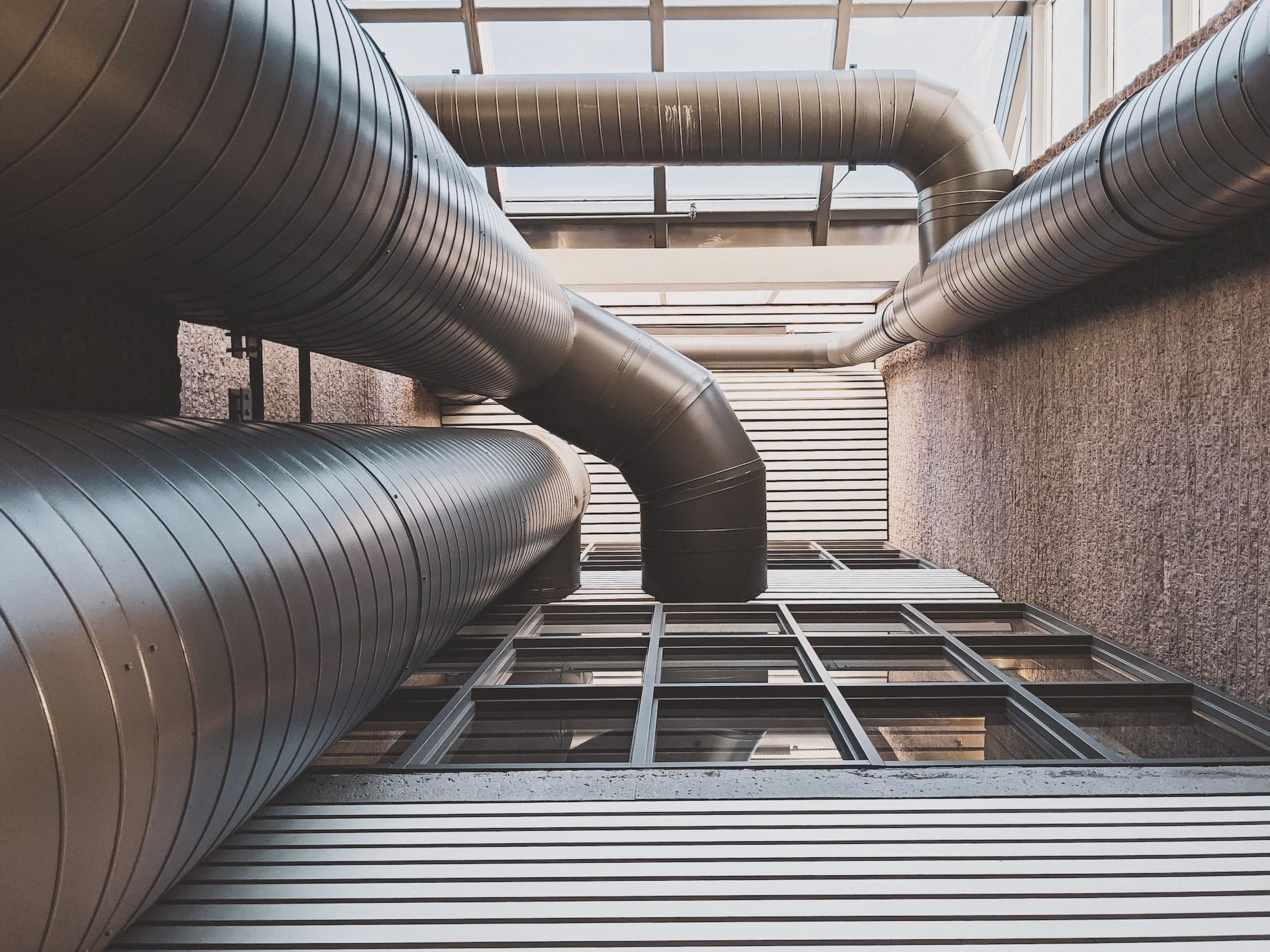
Heating and Cooling Systems
Contactors are used in heating and cooling systems to control the switching of heating and cooling elements, such as electric heaters, air conditioning compressors, and fans.
Power Distribution
Contactors can be used for power distribution in electrical switchgear and control panels, allowing for the switching and protection of high-current circuits.
Renewable Energy Systems
Contactors are commonly used in renewable energy systems, such as wind turbines and solar power systems, to control the switching and protection of high-current circuits.


Industrial Machinery
Contactors can be used in various industrial machinery, such as manufacturing equipment, conveyor systems, and packaging machinery, to control the switching and protection of high-current circuits.
Elevators and Escalators
Contactors are used in elevator and escalator systems for controlling the switching and protection of high-current circuits that power the motor and other electrical components.

Conclusion
Contactors are an essential component of many electrical circuits. They are available in a range of sizes and configurations to suit different applications and electrical systems. Contactors are designed to operate reliably and safely for many years, making them a popular choice for a variety of applications.
Need help searching and selecting the appropriate contactors for your project? Let us know! Our team will gladly help answer any questions you may have. Simply click on the widget above to complete a quick survey, and our team will get back to you as soon as possible.